Powering Your Project with STP14NK60Z: A Comprehensive Guide
Whether you're building a motor controller, a power supply, or any other electronic circuit that involves high-voltage and high-current switching, you need a robust and reliable power transistor to handle the load. One such option is the STP14NK60Z, a N-channel MOSFET device that can switch up to 14 Amps and withstand up to 600 Volts of drain-source voltage.
In this guide, we'll take a closer look at the STP14NK60Z and how it works, how to select it for your project, how to design the supporting components, how to simulate and test the circuit, and how to optimize its performance.
Introduction to STP14NK60Z
The STP14NK60Z is a member of STMicroelectronics' MOSFET Power Transistor family, which combines high drain-source breakdown voltage, low on-state resistance, and fast switching speed. The STP14NK60Z has a gate-source voltage threshold of 4 Volts, a drain-source on-state resistance of 0.25 Ohms, a gate charge of 40 nC, and a maximum drain current of 14 Amps at 25°C.
The STP14NK60Z comes in a TO-220FP package, which provides good thermal dissipation and easy mounting on a printed circuit board. However, it also requires proper heat sinking and isolation to avoid thermal and electrical failures.
How to Select STP14NK60Z for Your Project
To select the STP14NK60Z for your project, you need to consider several parameters, such as the input voltage, the output current, the switching frequency, and the ambient temperature. In general, the STP14NK60Z can handle a wide range of voltage and current levels, but the higher they are, the more attention you need to pay to the thermal and electrical constraints.
To calculate the power dissipation and junction temperature of the STP14NK60Z, you can use the following formulas:
Power dissipation = VDS x IDS + VGS x IG
Junction temperature = TA + (Power dissipation x RθJA)
Where VDS is the drain-source voltage, IDS is the drain current, VGS is the gate-source voltage, IG is the gate current, TA is the ambient temperature, and RθJA is the thermal resistance between the junction and the ambient.
You should also check the datasheet of the STP14NK60Z for the recommended operating conditions, the maximum ratings, and the electrical and thermal characteristics.
How to Design the Supporting Components
To ensure the proper functioning and protection of the STP14NK60Z, you need to design the supporting components, such as the gate driver, the snubber network, and the current sense resistor.
The gate driver is a circuit that provides the required voltage and current levels to switch the STP14NK60Z on and off quickly and cleanly. You can use a dedicated gate driver IC or build a discrete gate driver with transistors and diodes. The gate driver should be able to deliver a gate-source voltage higher than the threshold voltage of the STP14NK60Z, and a gate-source current that can charge and discharge the gate capacitance of the STP14NK60Z within the required time.
The snubber network is a circuit that reduces the voltage spikes and ringing that may occur during the switching of the STP14NK60Z, by adding a series capacitor and a parallel resistor across the drain and source terminals. The values of the capacitor and resistor depend on the parasitic impedances of the circuit and the switching frequency.
The current sense resistor is a small resistor that measures the current flowing through the STP14NK60Z, by sensing the voltage drop across it. The value of the current sense resistor depends on the desired accuracy and resolution of the current measurement, and the range of the current to be measured.
How to Simulate and Test the Circuit
Before building the actual circuit with the STP14NK60Z, you can simulate it using a SPICE simulator, such as LTSpice or PSpice. The SPICE model of the STP14NK60Z can be obtained from the STMicroelectronics website or other sources, and imported into the simulator. You can then create the schematic of the circuit, including the STP14NK60Z and the supporting components, and run the simulation under various conditions, such as different input voltages, load currents, and switching frequencies.
The simulation results can help you verify the performance and stability of the circuit, and identify any issues or improvements that need to be addressed. You can also use the simulation to optimize the values of the supporting components, and to compare the performance of different circuit topologies and control strategies.
After the simulation, you can proceed to test the circuit using a breadboard or a PCB prototype. You should check the wiring and connections, the polarity and orientation of the components, and the functionality of the circuit. You should also measure the voltage, current, and temperature at various points of the circuit, and compare them with the expected values.
How to Optimize the Performance
To optimize the performance of the circuit with the STP14NK60Z, you can consider several strategies, such as:
Using a heatsink or a fan to improve the thermal dissipation of the STP14NK60Z and increase its maximum current rating and reliability.
Implementing a soft-switching or zero-voltage switching technique to reduce the switching losses and increase the efficiency of the circuit.
Applying a pulse-width modulation (PWM) or other control technique to regulate the output voltage or current of the circuit according to the load and feedback signals.
Adding a protection circuit, such as a fuse, a diode, or a crowbar, to prevent overvoltage, overcurrent, or reverse voltage conditions that may damage the STP14NK60Z or the load.
By optimizing the performance, you can achieve a circuit that meets your requirements and exceeds your expectations in terms of efficiency, reliability, and cost.
Conclusion
The STP14NK60Z is a powerful and versatile MOSFET power transistor that can handle a wide range of applications, from motor control to power supply to lighting. By properly selecting, designing, simulating, testing, and optimizing the circuit with the STP14NK60Z, you can harness its capabilities and unleash your creativity and innovation.
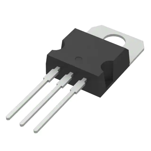
STP14NK60Z
- Part Number :
- STP14NK60Z
- Manufacturer :
- STMicroelectronics
- Description :
- MOSFET N-CH 600V 13.5A TO220AB
- Datasheet :
-
 STP14NK60Z.pdf
- Unit Price :
- Request a Quote
- In Stock :
- 3287
- Lead Time :
- To be Confirmed
- Quick Inquiry :
- - + Add To Cart
Request a Quote
STP14NK60Z Specifications
- Packaging:
- Tube
- Series:
- SuperMESH™
- ProductStatus:
- Obsolete
- FETType:
- N-Channel
- Technology:
- MOSFET (Metal Oxide)
- DraintoSourceVoltage(Vdss):
- 600 V
- Current-ContinuousDrain(Id)@25°C:
- 13.5A (Tc)
- DriveVoltage(MaxRdsOnMinRdsOn):
- 10V
- RdsOn(Max)@IdVgs:
- 500mOhm @ 6A, 10V
- Vgs(th)(Max)@Id:
- 4.5V @ 100µA
- GateCharge(Qg)(Max)@Vgs:
- 75 nC @ 10 V
- Vgs(Max):
- ±30V
- InputCapacitance(Ciss)(Max)@Vds:
- 2220 pF @ 25 V
- FETFeature:
- -
- PowerDissipation(Max):
- 160W (Tc)
- OperatingTemperature:
- -55°C ~ 150°C (TJ)
- MountingType:
- Through Hole
STP14NK60Z Guarantees

-
Service Guarantees
We guarantee 100% customer satisfaction.
Our experienced sales team and tech support team back our services to satisfy all our customers.

-
Quality Guarantees
We provide 90 days warranty.
If the items you received were not in perfect quality, we would be responsible for your refund or replacement, but the items must be returned in their original condition.
Certified Quality
 View the Certificates

