Unlocking the Full Potential of the ST72F324J2TAE Microcontroller
The ST72F324J2TAE microcontroller is part of the ST7 family of MCUs that have been used extensively in many electronic applications. It is a versatile device with various integrated peripherals and a cost-effective solution for small embedded systems. In this article, we’ll dive into the technical details of the ST72F324J2TAE and how to unlock its full potential.
Introduction to the ST72F324J2TAE
The ST72F324J2TAE is an 8-bit MCU that operates on a 5V power supply and has a maximum clock frequency of 8MHz. It features 32KB of flash memory, 1024 bytes of SRAM, and 256 bytes of EEPROM. The MCU includes a 16-bit timer/counter, a 10-bit ADC, two USARTs, a SPI interface, and a 3-channel PWM generator. It also has a built-in watchdog timer and low-voltage detector.
One of the key benefits of the ST72F324J2TAE is its low power consumption. The MCU is designed with a power-saving mode that can reduce power consumption to as low as 500nA. Additionally, the ST72F324J2TAE is a highly reliable and robust device that can withstand wide temperature and voltage ranges.
Programming the ST72F324J2TAE
To program the ST72F324J2TAE, you’ll need a programming tool that supports the ST7 architecture. You can use the ST-LINK/V2 programmer or the ST7FLITE programming kit. The ST72F324J2TAE is supported by many popular IDEs, including Keil, IAR, and Ride.
For beginners, it’s best to start with a simple LED blinking program. First, you need to set the data direction register of the output pin to output mode. Next, you need to set the pin state to high or low to turn on or off the LED. Here’s an example program in C language:
include
This program sets bit 7 of Port D as an output pin and blinks an LED connected to it. The main loop toggles the state of bit 7 and then waits for a short delay before repeating the process.
Using the Peripherals
The ST72F324J2TAE has various peripherals that are essential for many microcontroller-based applications. Here are some tips to utilize them effectively:
ADC
The ADC is a 10-bit successive approximation analog-to-digital converter that can measure voltage levels between 0 and 5V. It has four input channels and can be triggered by an internal or external source. To use the ADC, you need to set the input pins as analog mode through the corresponding data direction register and configure the ADC control register to specify the number of conversions and the trigger source. Here’s an example program to perform a single ADC conversion:
include
USART
The USART is a universal synchronous/asynchronous receiver/transmitter that can communicate with external devices using various communication protocols, such as UART, SPI, and I2C. The ST72F324J2TAE has two USARTs, USART1 and USART2, that can be configured independently. To use the USART, you need to set the corresponding pins as alternate function mode and configure the USART control registers to specify the communication parameters, such as baud rate, data format, and parity. Here’s an example program to send and receive data using USART1 in UART mode:
include
PWM
The PWM generator is a 3-channel pulse-width modulation that can be used for various purposes, such as controlling the speed of a DC motor or the brightness of an LED. To use the PWM, you need to set the corresponding pins as alternate function mode and configure the PWM control registers to specify the frequency and duty cycle. Here’s an example program to generate a PWM signal on channel 1 of the PWM generator:
include
Conclusion
In conclusion, the ST72F324J2TAE microcontroller is a versatile and reliable device that offers a cost-effective solution for many embedded systems. By understanding its technical details and utilizing its integrated peripherals effectively, you can unlock the full potential of this MCU and create innovative electronic applications. Whether you’re a beginner or an experienced developer, the ST72F324J2TAE is a valuable addition to your microcontroller toolbox.
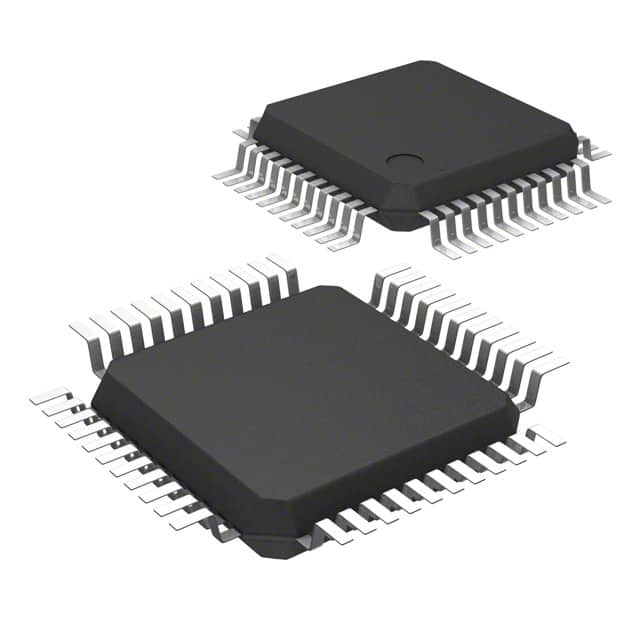
ST72F324J2TAE
- Part Number :
- ST72F324J2TAE
- Manufacturer :
- STMicroelectronics
- Description :
- IC MCU 8BIT 8KB FLASH 44LQFP
- Datasheet :
-
 ST72F324J2TAE.pdf
- Unit Price :
- Request a Quote
- In Stock :
- 3790
- Lead Time :
- To be Confirmed
- Quick Inquiry :
- - + Add To Cart
Request a Quote
ST72F324J2TAE Specifications
- Package/Case:
- 44-LQFP
- Packaging:
- Tray
- Series:
- ST7
- ProductStatus:
- RoHS
- CoreProcessor:
- 8MHz
- CoreSize:
- 384 x 8
- Speed:
- 8-Bit
- Connectivity:
- -
- Peripherals:
- Obsolete
- NumberofI/O:
- LVD, POR, PWM, WDT
- ProgramMemorySize:
- SCI, SPI
- ProgramMemoryType:
- Surface Mount
- EEPROMSize:
- 32
- RAMSize:
- ST7
- Voltage-Supply(Vcc/Vdd):
- A/D 12x10b
- DataConverters:
- Internal
- OscillatorType:
- 8KB (8K x 8)
- OperatingTemperature:
- FLASH
- MountingType:
- -40°C ~ 85°C (TA)
ST72F324J2TAE Guarantees

-
Service Guarantees
We guarantee 100% customer satisfaction.
Our experienced sales team and tech support team back our services to satisfy all our customers.

-
Quality Guarantees
We provide 90 days warranty.
If the items you received were not in perfect quality, we would be responsible for your refund or replacement, but the items must be returned in their original condition.
Certified Quality
 View the Certificates

